In this example, we will be wiring a SPKR-TAV to a recorder. When a camera triggers motion detection, the SPKR-TAV will trigger.
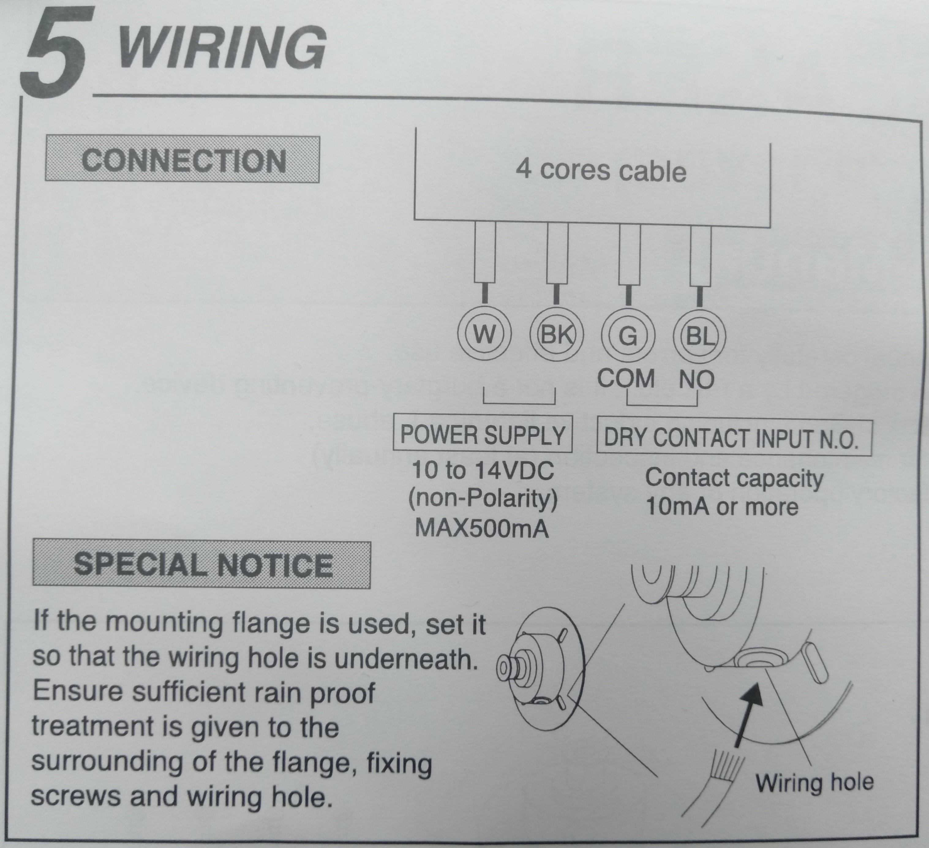
This is the wiring diagram for the SPKR-TAV. As you can see, the cable will have four coloured wires.
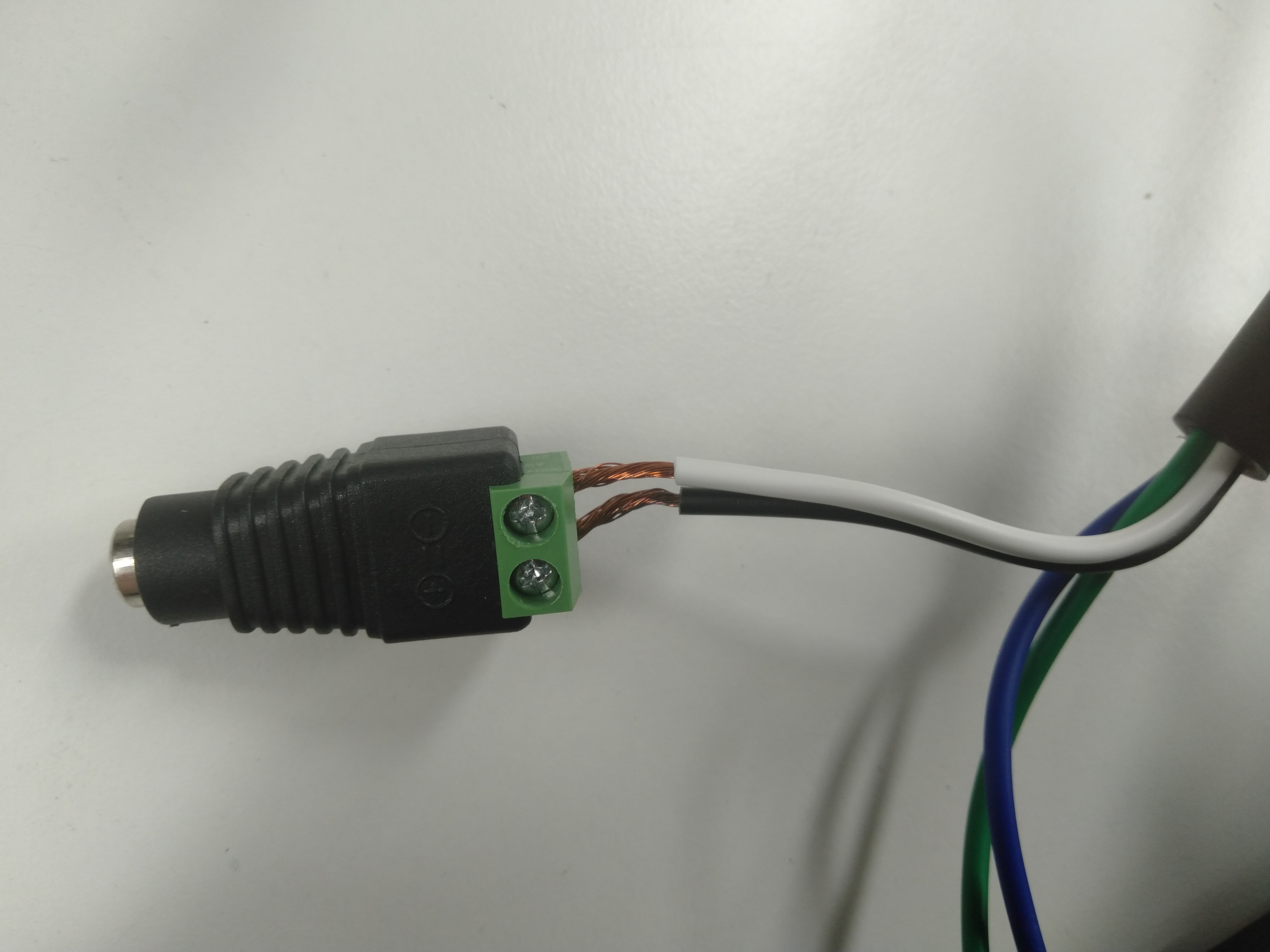 |
The Black & White cables needs to be connected to a power supply. |
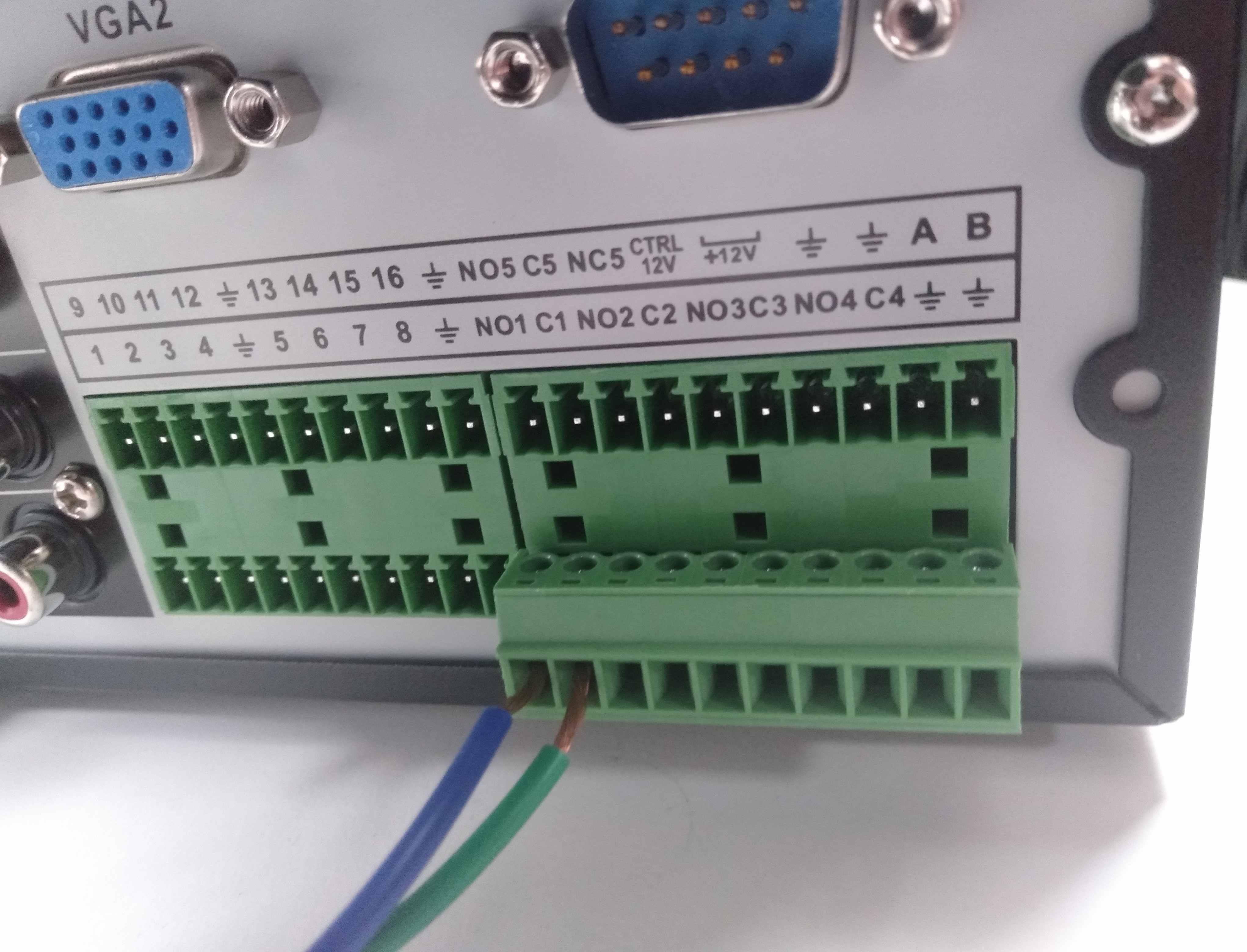 |
The Green and Blue wires go to the Alarm Output on the back of the Recorder.
The Blue wire goes to NO (Normally Open)
The Green Wire goes to C / COM (Common) Make sure the number at the end is the same.
(e.g Blue wire into NO1 & Green into C1) |
(Black GUI) Recorder Setup
Navigate to Main Menu > Alarm > Video Detection > Motion Detect
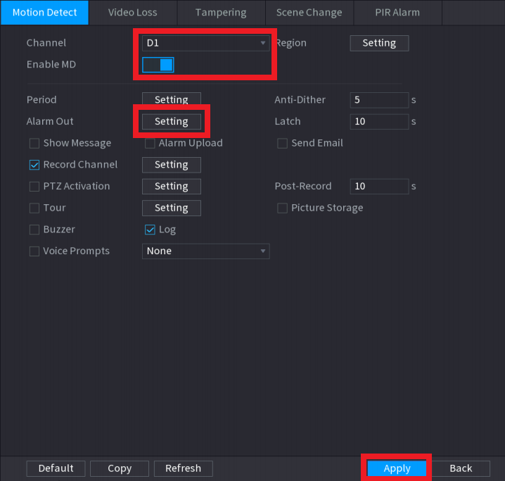
For each camera you wish to enable an Alarm Output for Motion Detection, do the following:
- Select the Camera Channel
- Tick Enable
- Click Setting next to Alarm Out, then select the Alarm Out channel number. This needs to match the number the Green & Blue wires are connected to. (e.g Alarm Out Channel 1 will activate NO1 & C1)
- Select Apply
(Blue GUI) Recorder Setup
Navigate to Main Menu > Event > Video Detection > Motion Detect
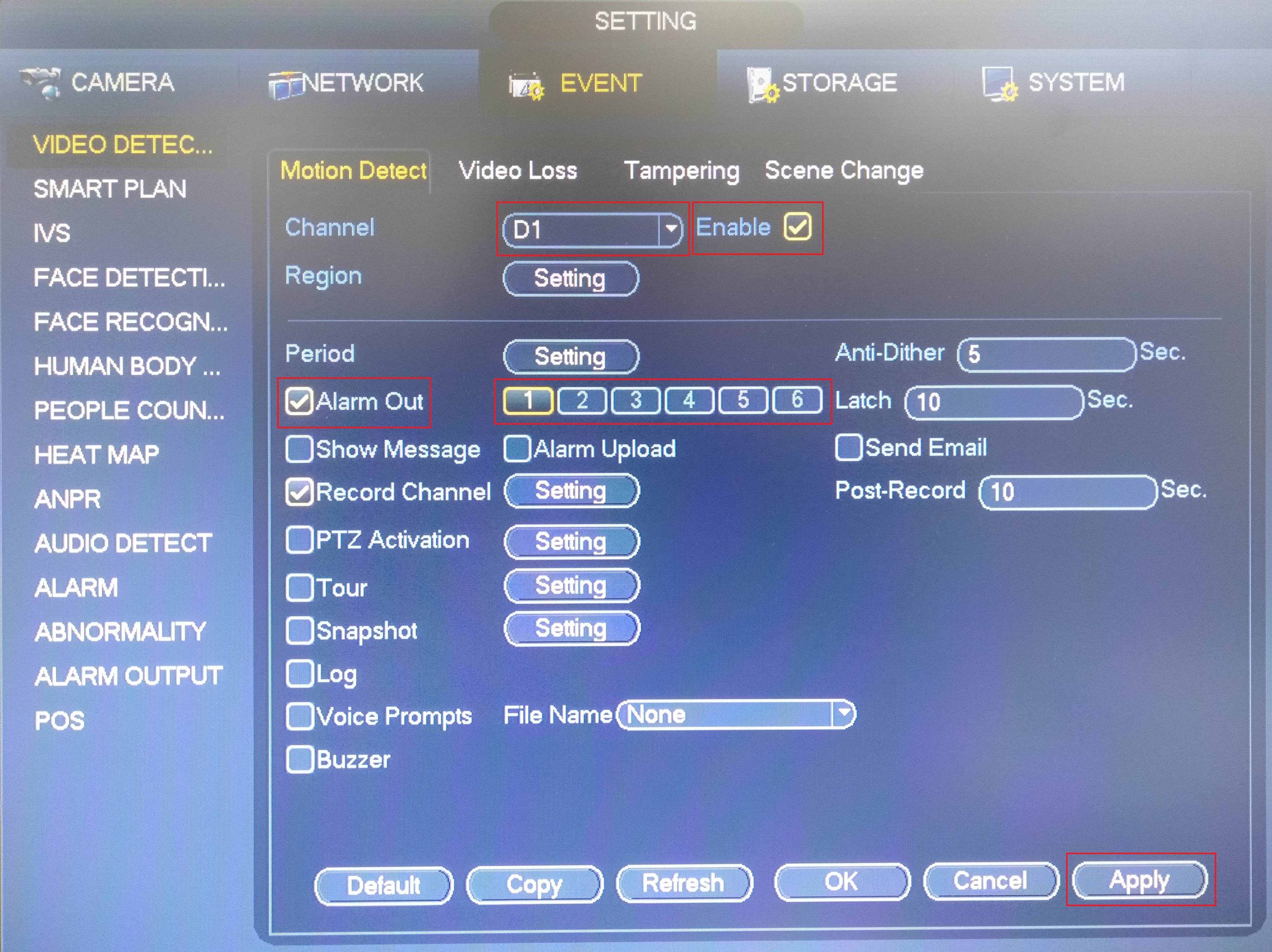
For each camera you wish to enable an Alarm Output for Motion Detection, do the following:
- Select the Camera Channel
- Tick Enable
- Tick Alarm Out
- Enable Alarm out and select the Alarm Out channel number. This needs to match the number the Green & Blue wires are connected to. (e.g Alarm Out Channel 1 will activate NO1 & C1)
- Select Apply