What can you use the alarm Outputs for ?
They can be used multiple different ways, such as detecting loss of cameras, HDD & Network.
- Activate a Floodlight On Schedule/Manually triggered / IVS Tripwire & Intrusion / Motion Detection / AI Human & Vehicle Detection
- Activate PTZ Tour, Move PTZ to Pre-set
- Connect alarm output to Hardwired Alarm Panel to set off alarm when a camera is triggered
What can you use the alarm Inputs for ?
You can also connect sensors such as a PIR, microwave sensors & smoke detectors to the alarm input. When the sensor is triggered the alarm output is activated which then can be used to trigger other devices.
(Black Interface) Alarm Settings
The Alarm settings are located at Main Menu > Alarm > Alarm Input
(Blue Interface) Alarm Settings
The Alarm settings are located at Main Menu > Event > Alarm

Settings Overview - Input Channel Trigger & Settings
Alarm In: Selects which Alarm input is being configured.
Alarm Name: Reference Name for alarm input.
Type: N.O / N.C Relay Type
Period: Active hours for alarm input
Anti Dither: Allows a present time where subsequent triggers will be ignored, prevents multiple event triggers during this period.
Alarm Out: Enable an output if an input is triggered.
Latch: How long the event lasts, default 10 seconds.
Show Message: Display a Message on the Main Screen of the NVR when an alarm event is created.
Alarm Upload: Can be used to send network alerts to a Monitoring Centre, generally not used.
Send Email: Will send an email about the event to the pre configured email.
Record Channel: Record footage for alarm events as Red, instead of the usual Green for normal recording, allows search by filtering for only alarm events.)
PTZ and Tour Activation: Activate PTZ preset/tour. (The preset/tour must already have been configured)
Post Record: How long recording will continue after the event has occurred.
Voice Prompts: Play an Audio file, this can be uploaded to the recorder via USB.
Alarm Output: Activate the onboard relay to trigger an external device.
Alarm Upload: Used for alarm event upload to monitoring centre, not used.
Buzzer: Activate internal speaker when event is triggered.
Picture Storage: Take a snapshot of the alarm event
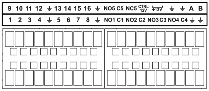
Alarm Input/Output connection terminals
Below is an overview of the terminology you can will see on the alarm terminals. This exact configuration varies from model to model, but the terminology will be the same.
1-16 = 1-16 Alarm Input Channels
NO1 C1 = Normally Open Relay #1
NC1 C1 = Normally Closed Relay #1
NO1 C1 NC1 = N.O OR N.C Relay #1
INPUTS OUTPUTS 
Wiring Diagram
In the below diagram, one reed switch has been wired to Alarm Input 1, and an external power supply and relay have been wired to Alarm Output 1 to trigger a 12V Device (e.g. Siren). This has been wired in the Normally Open configuration.
